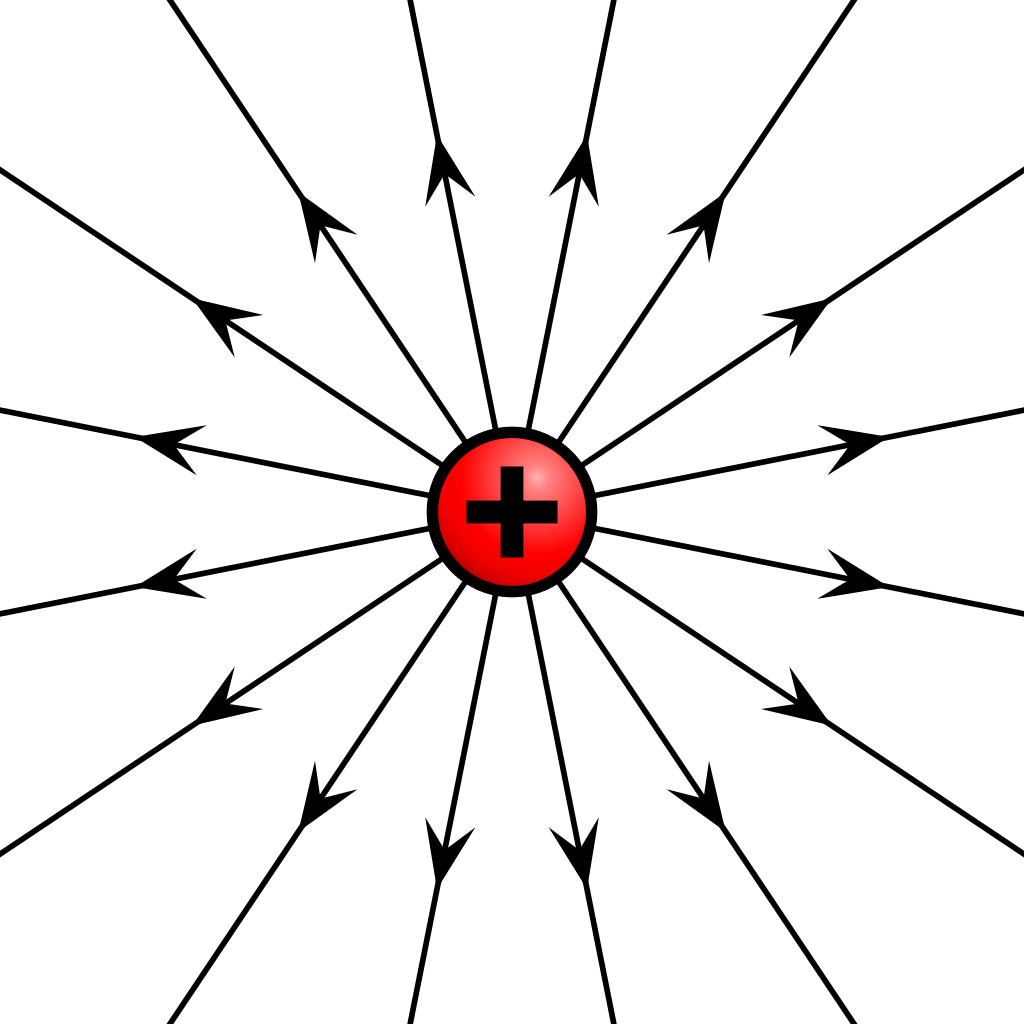
An electric field \(\overrightarrow{E}\) is defined as \(\frac{\overrightarrow{F}}{q}\) where \(\overrightarrow{F}\) is the electric force and \(q\) is the charge. The shape of the force lines in an electric field changes depending on the shape and interactions that an object goes through, this means that for a point charge such as an electron or a proton, the direction of the electric field is set by the charge. For a positive point charge, the electric field has the same direction as the electric force, pointing outwards.
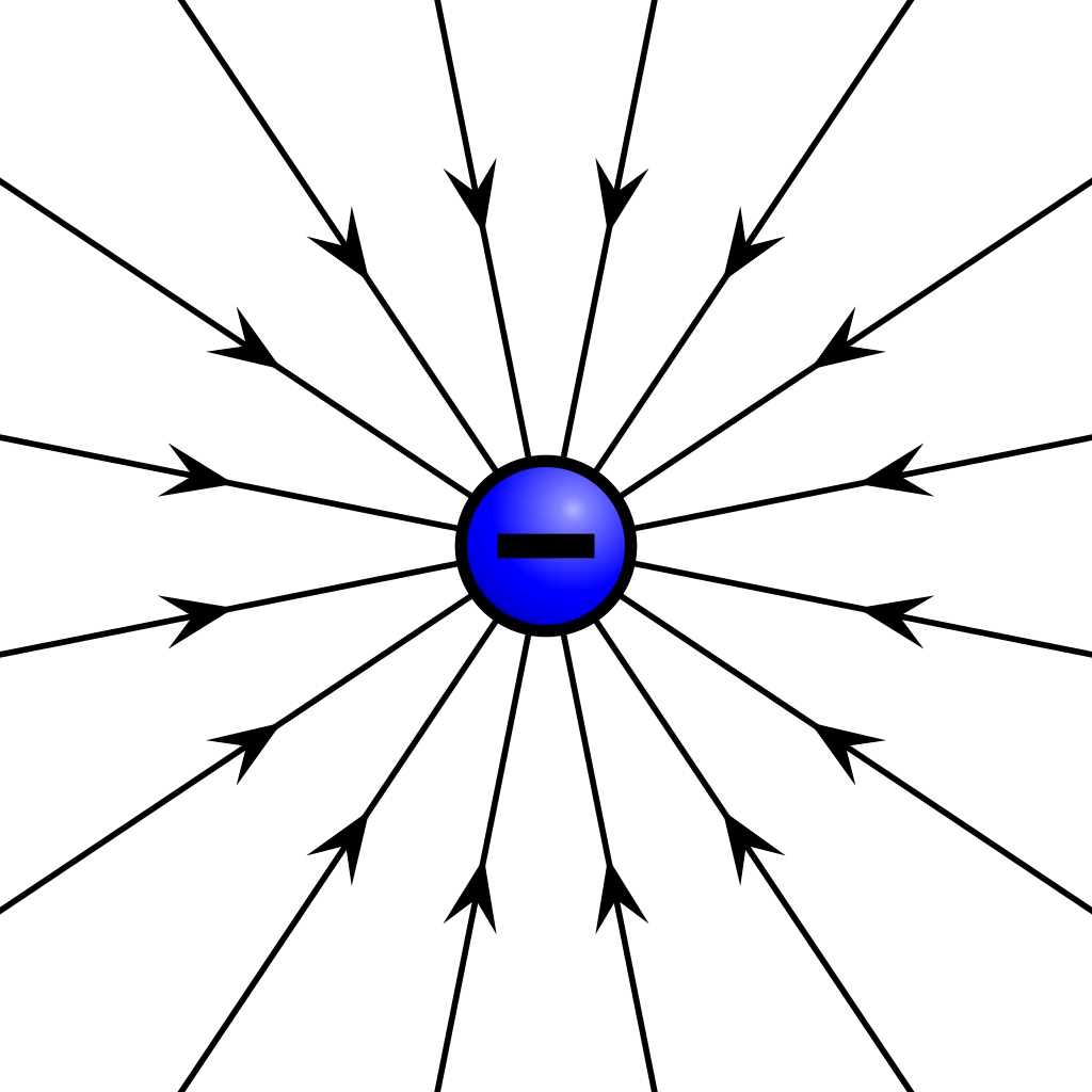
And for a negative charge, the electric field goes in the opposite direction of the electric force, pointing inwards to the charge
The magnitude of these point charges is calculated by using Coulomb’s law, which states that the electric force magnitude between two point charges is equal to:
\[|\overrightarrow{F}|=k\frac{Qq}{r^{2}}\]where \(Q\) is the first charge, \(q\) the second charge, \(r\) the distance between them, and \(k\) is the Coulomb’s constants that is equal to \(\frac{1}{4\pi \epsilon_0}=9\cdot10^{9}\frac{N\cdot m^{2}}{C^2}\) where \(\epsilon_0\) is the permittivity of space.
Solving the electric field for a point charge by replacing \(\overrightarrow{F}\) in \(|\overrightarrow{E}|\) we get:
Line charge
We can calculate the electric field of any shape by representing it as the continuous distribution of point charges across the surface of that shape even though the charge is quantized, the total number of charges on the surface can be so large that we could consider it to be continuous. For example, if we want to know what is the magnitude of an electric field of a line at some point in the space, we need to represent that line with charge \(q\) as a group of almost infinite \(\lambda\) point charges across its length.
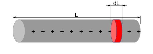
This \(\lambda\) is the value of the charge density, how many \(C\) are there per unit length \(\lambda=\frac{q}{L}\), by this we can say the charge \(dl\) of the segment is equal to \(\lambda dl\), and then we can define the electric field magnitude \(dE\) of the \(dQ\) point charge as:
\[dE=k\frac{\lambda dl}{r^{2}}\]Where \(r\) is the distance from that particular point charge. In order to obtain that full vector we make use of the superposition principle which states: “Every charge in space creates an electric field at point independent of the presence of other charges in that medium. The resultant electric field is a vector sum of the electric field due to individual charges.” basically what we need to do here is add up every \(dQ\)’s electric field forming the following expression:
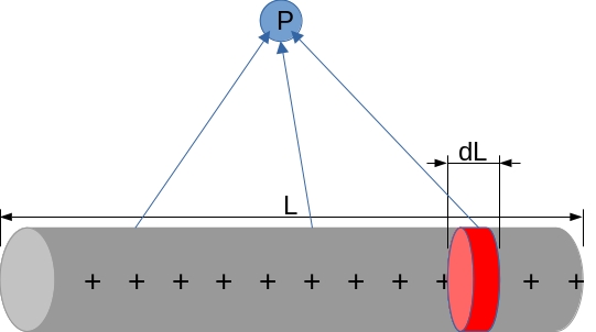
\[E=k\int_{a}^{b}\frac{\lambda dl}{r^{2}}\]Okay, we got the expression, but something is missing. Electric field changes according to the distance, so how do we add up almost infinite different distance dependent values? Well if we want to take a measure of the electric field from a point \(P\)
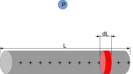
If we draw lines from the point \(P\) towards some \(dL\) charges and it forms an angle from the start and the end of the line charge
But wait, what if we split it from the middle? This way a right triangle will form, and we will be able to use trig identities to form a new integral
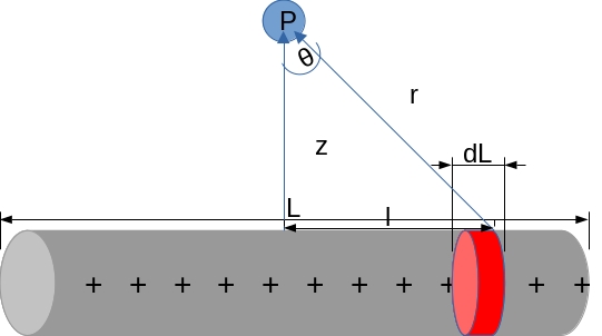
Via trigonometric substitution we change \(dl\) in terms of the angle \(d\theta\) by first finding what’s the value of \(l\)
\[cos\space\theta=\frac{z}{r}\Rightarrow r=z\frac{1}{cos\space\theta}=z\space sec\space\theta\Rightarrow r^{2}=z^2sec^2\space\theta\\ tan\space\theta=\frac{l}{z}\Rightarrow l=z\space tan\space\theta\]Derivating \(l\) in terms of \(\theta\) gives us:
\[dl=z\space sec^{2}\space\theta\space d\theta\]After doing the substitution for \(dl\) and \(r\) we get:
\[\frac{dl}{r^{2}}=\frac{z\space sec^{2}\space\theta\space}{z^2sec^2\space\theta}d\theta = \frac{1}{z}d\theta\]Going back to the integral we can form an expression that sweeps the whole line across the angle
\[k\int_{-\theta}^{\theta} \frac{\lambda}{z}\space\cos\theta\space d\theta\]By this aproach we can find the electric field at the \(z\) axis of the symmetry point of any shape, even thought that is not the goal this time, it is important to know as a basis for the following.
Simulating electric field lines
For the lab report of this class, we were asked to put a simulation of what kinds of electric field lines with different shapes of charges like line, point, and a ring would have, at the time no one on my team would know how to do that and luckily I found a page that did that and a teammate just did some photoshop magic to form the ring charge(https://static.bcheng.me/electric-fields/). Fortunately, the less-idiot-me of today finally understands how the superposition principle can be used for this problem (also the even lesser-idiot-me knows that just a drawing that shows for example the ring electric field would be like a point charge on the outside and a -point charge on the inside ).
According to the sources I’ve read, we can represent an empty electric field space with vectors that point outwards from the origin, these vectors will suffer a transformation by adding all-electric fields surrounding it. For this simulation I’ll be using GNU Octave, first I wrote the code to create that space:
clear; close all; clc;
%grid
N=30; %density
minX=-20;maxX=+20; %grid size
minY=-20;maxY=+20;
xl=linspace(minX,maxX,N); %evenly spaced N vectors per row
yl=linspace(minY,maxY,N);
global xS;
global yS;
global Ex;
global Ey;
[xS,yS]=meshgrid(xl,yl); %vector grid

u=xS;
v=yS;

h=quiver(xS,yS,u,v,'autoscalefactor',0.6);
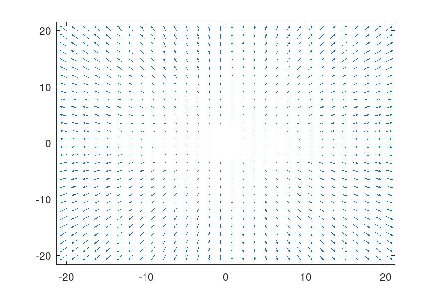
By using the dipole moment formula \(\overrightarrow{E}_{dipole}=k\frac{\overrightarrow{p}}{z^{3}}\) we can compute an electric field by just adding up the electric fields of point charges, for this I just made a function that calculates the electric field at some point (x,y)
%electric field components
Ex=0;
Ey=0;

%q=charge x,y=position in the grid
function efield = place_charge(q,x,y)
  global xS;
  global yS;
  global Ex;
  global Ey;
  %constants
  eps0 = 8.854e-12;
  k = 1/(4*pi*eps0);
  %vector coordinates in the spaces where the point charge is placed
  Cx = xS-x;
  Cy = yS-y;
  C = sqrt(Cx.^2 + Cy.^2).^3;
  %electric field calculation
  Ex = Ex + k .* q .* Cx ./ C;
  Ey = Ey + k .* q .* Cy ./ C;
end
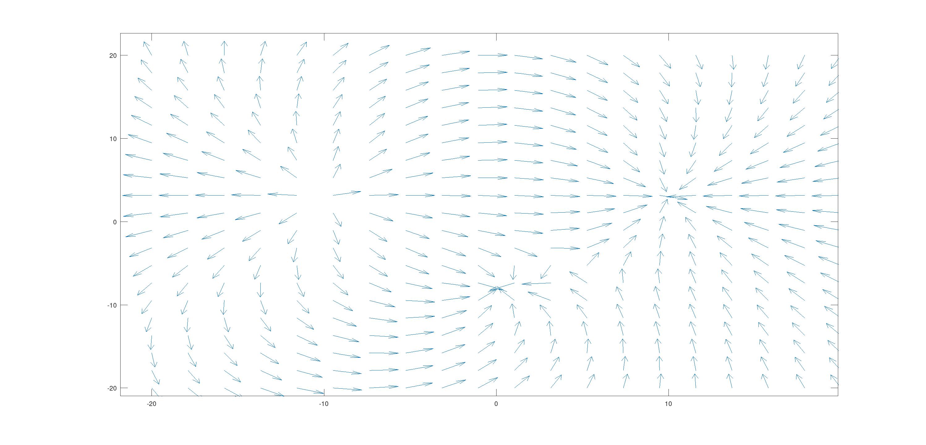
This is the result with some charges added to the grid (after changing u and v to the normalized components of Ex and Ey)
Shaped charges
Now that we know that \(\overrightarrow{E}_{final}\) is just the sum of all point charge electric fields, for the simulation we can make new functions that keep adding point charges across the desired shape. This new function places point charges across a line from two points (I forgot to implement when y0=y1 lol).
function linefi = place_line(q,x0,y0,x1,y1)
  %calculate the steps and the charge of each element
  lambda = q ./ sqrt( (x1-x0).^2 + (y1-y0).^2);
  step=abs(lambda);

  %slope
  dx=x1 - x0;
  dy=y1 - y0;
  m=dy ./ dx;
  b=y0 - m .* x0;

  if x1==x0
    %Do sweep across y axis only
    if(y0>y1)
    step*=-1;
  endif
  for i = y0:step:y1
    disp(i);
    place_charge(lambda,x0,i);
  end
  else
    %Do sweep across xy axis
    if(x0>x1)
      step*=-1;
    endif
    for i = x0:step:x1
      disp(i);
      place_charge(lambda,i,m.*i + b); %y = mx+b
    end
  end
end
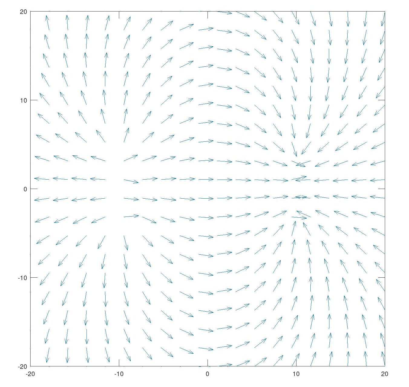
This is what two parallel lines electric fields look like:
Now, for the final shape we were asked how its electric field would look like, the ring. For this one I just need to place \(\frac{q}{2\pi r}\) charges around a circle at \(r\) distance from a point that will be our center (\((x_0+r\space\cos\space\theta,y_0+r\space\sin\theta)\) basically)
function ringfi = place_ring(q,x,y,r)
  lambda = q ./ (6.28318530717958647693.*r);
  lambda
  step=abs(lambda);
  for i=0:step:6.28318530717958647693
    disp(i);
    place_charge(lambda,x+r*cos(i),y+r*sin(i));
  endfor
end
This is what it looks like (also at this point I added a visual aid to the place_charge function)
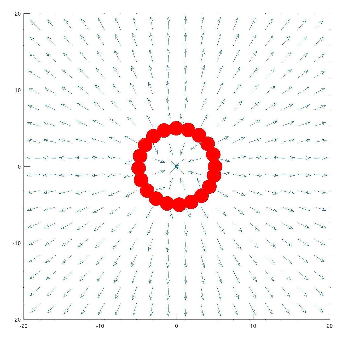
Here is the full code for those who want to play with it
clear; close all; clc;
%grid
N=20; %density
minX=-20;maxX=+20; %grid size
minY=-20;maxY=+20;
xl=linspace(minX,maxX,N); %evenly spaced N vectors per row
yl=linspace(minY,maxY,N);
global xS;
global yS;
global Ex;
global Ey;
[xS,yS]=meshgrid(xl,yl); %vector grid

%electric field components
Ex=0;
Ey=0;
%q=charge x,y=position in the grid
function efield = place_charge(q,x,y)
  global xS;
  global yS;
  global Ex;
  global Ey;
  %constants
  eps0 = 8.854e-12;
  k = 1/(4*pi*eps0);
  %vector coordinates in the spaces where the point charge is placed
  Cx = xS-x;
  Cy = yS-y;
  C = sqrt(Cx.^2 + Cy.^2).^3;
  %electric field calculation
  Ex = Ex + k .* q .* Cx ./ C;
  Ey = Ey + k .* q .* Cy ./ C;

  hold on;
  if(q<0)
  plot(x, y, 'b', 'MarkerSize', 80);
else
  plot(x, y, 'r', 'MarkerSize', 80);
  end

end

function linefi = place_line(q,x0,y0,x1,y1)
  lambda = q ./ sqrt( (x1-x0).^2 + (y1-y0).^2);
  step=abs(lambda);
  dx=x1 - x0;
  dy=y1 - y0;
  m=dy ./ dx;
  b=y0 - m .* x0;
  if x1==x0
    %Do sweep across y axis
    if(y0>y1)
    step*=-1;
  endif
  for i = y0:step:y1
    place_charge(lambda,x0,i);
  end
  else
    %Do sweep across x axis
    if(x0>x1)
      step*=-1;
    endif
    for i = x0:step:x1
      place_charge(lambda,i,m.*i + b); %y = mx+b
    end
  end
end

function ringfi = place_ring(q,x,y,r)
  lambda = q ./ (6.28318530717958647693.*r);
  lambda
  step=abs(lambda);
  for i=0:step:6.28318530717958647693
    disp(i);
    place_charge(lambda,x+r*cos(i),y+r*sin(i));
  endfor
end

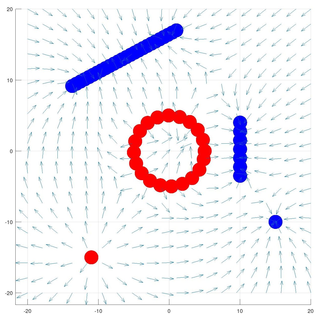
place_ring(10,0,0,5);
place_line(-10,10,4,10,-4);
place_charge(-5,15,-10);
place_line(-10,1,17,-14,9);
place_charge(10,-11,-15);

%normalize transforms
E = sqrt(Ex.^2 + Ey.^2);
u = Ex./E;
v = Ey./E;

quiver(xS,yS,u,v,'autoscalefactor',0.6);
hold on
axis([-20 20 -20 20]);
axis equal
Visualizing the field in the real life
There is a experiment everyone can try to visualize the electric field of any shape without having to solve boring integrals or things like that, for this you will need:
- A power supply of at least 12v
- Cooking oil
- Canary grass
- A tray
- Thick wires that you will shape however you want
- Thiner wires to connect the thicker ones to your power supply
In class we had a Wimshurst machine as our power supply because before doing this we were calculating the charge of two electrostatic charged pendulums (and testing if condoms are truly nonporous lol)
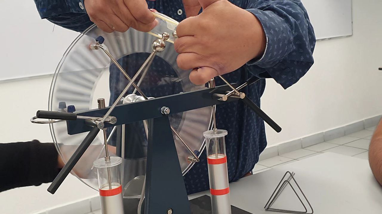
Put the oil on your tray, shape your wires, connect them to your power supply, sprinkle some canary grass and crank the voltage up
And that’s it. They actually look like the simulations (with the difference that we didn’t have to solve math for this one hehe). For the next post, I’ll continue this topic with equipotential lines.